Arduino Nano I2C - Arduino Nano Dht11 Temperature And Humidity I2c 2 X 16 Lcd Display With Visuino 13 Steps Instructables - The arduino® nano rp2040 connect is a development board in nano format, based on the rp2040 microcontroller.
Get link
Facebook
X
Pinterest
Email
Other Apps
Arduino Nano I2C - Arduino Nano Dht11 Temperature And Humidity I2c 2 X 16 Lcd Display With Visuino 13 Steps Instructables - The arduino® nano rp2040 connect is a development board in nano format, based on the rp2040 microcontroller.. Each i2c bus consists of two signals: I am having trouble with the nano i2c wire library. With the answers to the following 3 questions, i believe i can make progress. Hi there,welcome to our instructables page. All cables tested and work:
I am using a genuine arduino nano v3.0 and the standard wire library. All cables tested and work: For uno, it gave the same results for 2x16 and 4x20 but not for nano every. Connect the black jumper cable from the gnd pin on the lcd to the bnd pin on the nano. Below are the images obtained from i2cexpdiag.
Can T Get I2c To Work On An Arduino Nano Pinout Diagrams Big Dan The Blogging Man from christianto.tjahyadi.com The code segment below is a complete sketch ready for downloading to your arduino. Atmega328p microcontroller used in arduino uno and nano supports i2c data transfer speeds up to 400 khz. Also, be aware that there are some incorrect hookup diagrams on the internet for the pro mini. I am having trouble with the nano i2c wire library. Hi there,welcome to our instructables page. With the answers to the following 3 questions, i believe i can make progress. The bus has 2 wires one is sda through which data is transmitted and received. 1602 , featured 1602 lcd直接繋ぐと、6つのデジタルポートを占有(4つデータワイヤ+2の制御ワイヤが必要)し、gpioはたくさん消耗するので、i2cを利用すると2つのアナログポートが足りる。
Because the oled display uses i2c communication protocol, wiring is very simple.
Place the nano on the solderless breadboard. Hi there,welcome to our instructables page. I have found a document showing the i2c pins on arduino nano as a4 and a5 and another says they are d4 and d5. For uno, it gave the same results for 2x16 and 4x20 but not for nano every. I found a pinout diagram for the arduino nano which clearly indicates that the sda and the scl pins on the nano are the a4 and the a5 pins. First we will mention how to set up an arduino as either a master or a slave. However, wiring between arduino and the normal lcd is complicated. The model we're using here has only four pins and communicates with the arduino using i2c communication protocol. I had some confusion initially but later found out that sda and scl on arduino nano are available on a4 and a5 pins. The arduino nano uses gpio a4 (sda) and a5 (scl) for i2c. To demonstrate the working of i2c in arduino, let us build a small circuit. The clock signal is always generated by the current bus master; To simplify the use of the i2c protocol, arduino uses the wire library, which allows you to implement and use this protocol throughout different arduino boards.
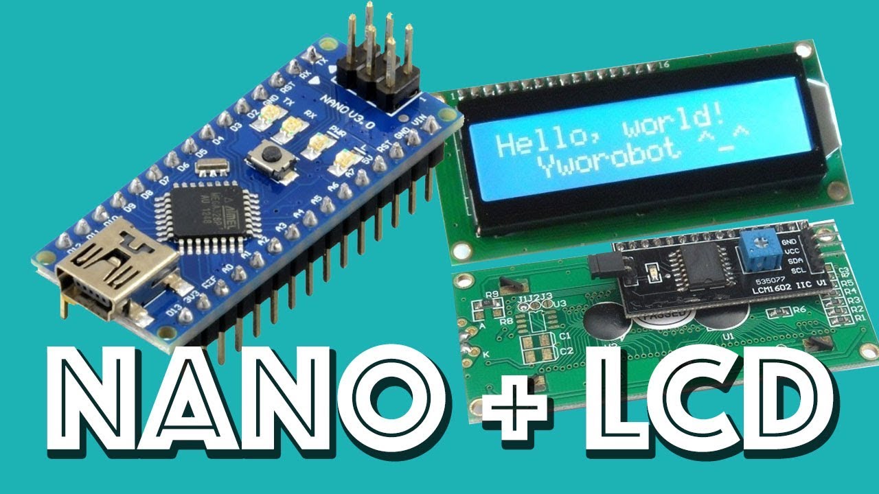
In this demo, i connected two arduino uno boards to communicate over i2c bus. Analogue pins can function as an analogue to digital converter and a4 and a5 pins can be used for i2c communication. Lcd i2c uses i2c interface, so it has 4 pins: The arduino® nano rp2040 connect is a development board in nano format, based on the rp2040 microcontroller. Another is scl through which the master controller sends clock signals to peripheral devices.
Arduino Time Www Hoaglun Com from images.squarespace-cdn.com I have found a document showing the i2c pins on arduino nano as a4 and a5 and another says they are d4 and d5. Place the nano on the solderless breadboard. After the basics are explained we will show an example how to b… Use a text editor to create the program, raspbian comes with a few of them. It is designed to reflash the mega328p with code residing in an external i2c memory or another i2c device. Note that the arduino due actually has two i2c ports. However, wiring between arduino and the normal lcd is complicated. In this tutorial, i will show you how easy it is to connect ds1307 i2c rtc module to arduino, and read the time from it with.
Place the nano on the solderless breadboard.
The code segment below is a complete sketch ready for downloading to your arduino. Rather, arduino refers to a whole family of boards like arduino uno, arduino nano, arduino pro mini, arduino mega, and so on, you can check a complete list of the arduino avr boards, simply open the arduino ide, click on the tools menu and then boards. If your card is not a mega r3, use only connectors 20 and 21. I want to warn here for false documentation due to wrong pinout description for arduino nano. To use this library, open the library manager in the arduino ide and install it from there. Therefore, lcd i2c has been created to simplify the wiring. Also, be aware that there are some incorrect hookup diagrams on the internet for the pro mini. They come with a clock and a small battery, and when connected to arduino, can keep track of real time even when the arduino board is not powered. For testing, cat24m01 1mbit (128kbyte) external eeprom was used. Using the arduino i 2 c address scanner, it is unable to find a device, even though it is wired correctly (i've checked multiple times). For our first experiment we will hoo two arduinos together and exchange data between them. This is the code i used, i2c_scanner, and this output: In this instructable you are going to see how to connect i2c lcd display to arduino and how to print on lcd display.
I am using a genuine arduino nano v3.0 and the standard wire library. The model we're using here has only four pins and communicates with the arduino using i2c communication protocol. Port i2c on arduino mega board. How to use arduino i2c interface? Therefore, lcd i2c has been created to simplify the wiring.
How To Connect An I2c Lcd Display To An Arduino Nano Youtube from i.ytimg.com I am using a genuine arduino nano v3.0 and the standard wire library. They come with a clock and a small battery, and when connected to arduino, can keep track of real time even when the arduino board is not powered. I am having trouble with the nano i2c wire library. To demonstrate the working of i2c in arduino, let us build a small circuit. For testing, cat24m01 1mbit (128kbyte) external eeprom was used. Below are the images obtained from i2cexpdiag. A library for i2c lcd displays. With the answers to the following 3 questions, i believe i can make progress.
How to connect an i2c lcd display to an arduino nanoi2c scanner :
They come with a clock and a small battery, and when connected to arduino, can keep track of real time even when the arduino board is not powered. I want to warn here for false documentation due to wrong pinout description for arduino nano. For our first experiment we will hoo two arduinos together and exchange data between them. In this demo, i connected two arduino uno boards to communicate over i2c bus. Lcd i2c uses i2c interface, so it has 4 pins: This project will read the position of a potentiometer connected to a master arduino, send the information over i2c, and change the blink rate of the led on the slave arduino. Port i2c on arduino mega board. Right now i am running in circles. Getting tiny tetris running on a 128x64 oled display using an arduino nano or uno. If your card is not a mega r3, use only connectors 20 and 21. Using the arduino i 2 c address scanner, it is unable to find a device, even though it is wired correctly (i've checked multiple times). After the basics are explained we will show an example how to b… Connect the red jumper cable from the vcc pin on the lcd to the vcc pin on.
It is an i2c bootloader for arduino, tested on atmega328p arduino nano. Scl is the clock signal, and sda is the data signal.


Comments
Post a Comment